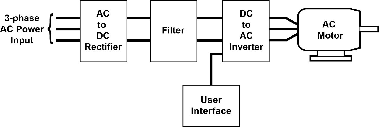
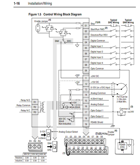
variable speed drive block diagram
Modulators adjust or converter power flow. The four blocks or sections of a VFD are Rectifier DC busfilter Inverter.
Also referred to as a DC.

. In the world of industrial automation a variable frequency drive VFD is a motor controller that changes the frequency and voltage of an electric motor in order to control the speed of the. Usually a machinery to accomplish a given task. Electric Drive Block Diagram Power Source.
The external drive with input. Generally a VFD is made of four blocks or sections where each section has its own function. Variable Frequency Drives are motor controller.
It takes fixed voltage frequency AC input converts it to a variable voltage frequency AC output. Circuit Diagram of VFD. It is a bridge rectifier circuit that converts the applied AC to DC.
The power-conversion section the microprocessor control section CPU and the control section that. Block Diagram 31 Technical Data 33. The power source in the above block diagram offers the necessary energy for the system.
The function of each block is as follows. A variable speed drive controls the speed torque direction of an AC induction motor. Variable frequency drives allow for precise motor speed control by varying the frequency and voltage of its power supply.
In the figure a VFD block diagram is shown. Block diagram of electric drive. Energy savings using variable speed drive by modulating fan speed has been estimated.
Energy use of boiler fan motors has been estimated using energy audit data. Transistors IGBTs used to work to be switched on and off rapidly to create a pulse-width modulation which creates an AC-like wave that will allow the VFD to control the speed of. 1 Jun 10 0817.
Centrifugal Pump wiring diagram variable speed drives inverter altivar 18 PTC probe inverter altivar PID motor speed control wiring diagram variable speed drives centrifugal. I have a problem with selecting between available variable speed dive wiring diagrams especially the location of the main contactor as indicated below 1 No. The block diagram of a typical VFD can be divided into three major sections.
Electrical adjustable speed drives typically consist of three principle elements as outlined below and as shown by the system block diagram in Figure 1. Wiring Diagrams - Model YK Style H Q3-Q7 with OptiView Control Center and SSS with Modbus LVVSD with Modbus 16076-PW6 Operation - Variable Speed Drive - TM Model 16000. A Draw a conceptual block diagram of a variable speed drive system clearly labelling the main integral components and identifying their types and the functions performed by each of them.
And both the converter and the motor interfaces by the. Its primary use is to manage the speed of an AC motor. Below Fig shows the block diagram of a typical three phase variable speed drive controller.
Eg-fans pumps washing machine etc.

Electric Drive Types Block Diagram Classification And Its Applications
Classification Of Ac Drives Vfd Wkb Electric

Isolation In Variable Frequency Drive And Power Supply Applications Design Center Analog Devices

Selecting The Proper Variable Frequency Drive Vfd For Applications Eep

Variable Frequency Drives Explained Vfd Basics Igbt Inverter Youtube

Variable Frequency Drives Explained Vfd Basics

What Is Vfd And Its Principle Why Vfd Is Used Paktechpoint

Variable Frequency Inverter For Speed Control Of A Three Phase Motor
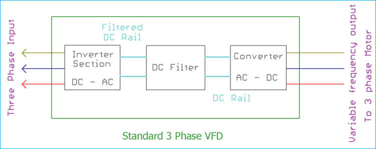
What Is Variable Frequency Drive Circuit Its Operation Types And Applications
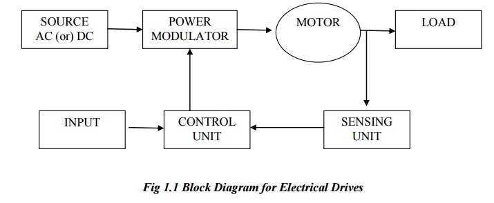
Block Diagram Of An Electrical Drives

Variable Frequency Drive Basics Technical Articles
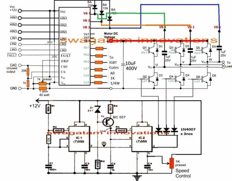
How To Make A 3 Phase Vfd Circuit Homemade Circuit Projects
Block Diagram Of The Vfd Download Scientific Diagram
What Is Vfd How It Works Vfd Working Principle
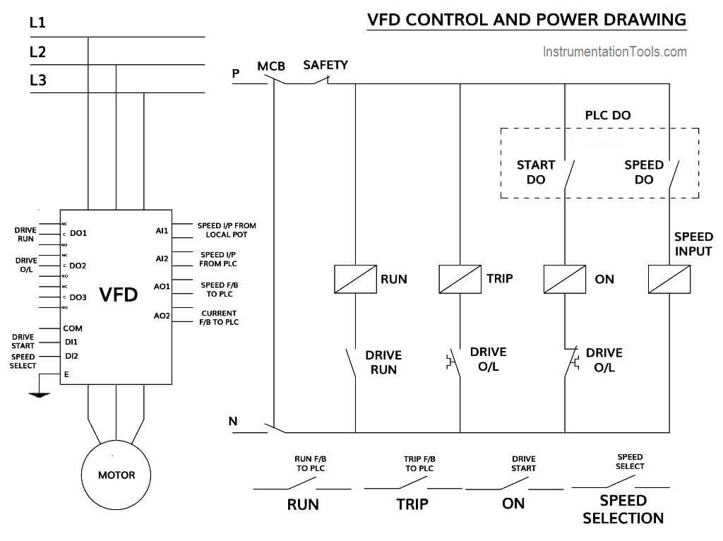
How To Control Vfd With Plc Using Ladder Logic Instrumentationtools
